Logic Families and Characteristics
A logic family is a group of digital ICs built with similar transistor technology and electrical behavior. Choosing the right family matters because voltage thresholds, output drive, speed, power, and input tolerance decide whether a digital system works reliably.
Learning Objectives
By the end of this lesson, you should be able to compare TTL and CMOS families, calculate noise margin and fan-out, estimate CMOS dynamic power, and choose safe interfacing methods between voltage domains.
TTL Families
TTL uses bipolar transistors and is historically associated with 5 V 7400-series logic. Common variants include standard 74xx, low-power Schottky 74LS, advanced low-power Schottky 74ALS, and fast 74F.
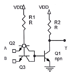
Typical 5 V TTL-compatible input limits are:
| Parameter | Typical guaranteed value |
|---|---|
VIL(max) |
0.8 V |
VIH(min) |
2.0 V |
VOL(max) |
0.4 V |
VOH(min) |
2.4 V |
TTL has modest noise margins and consumes more static current than CMOS, but it remains important for legacy systems and for understanding digital interface history.
CMOS Families
CMOS uses complementary NMOS and PMOS transistors. Static current is very low because one transistor in the pair is normally off in a stable state.
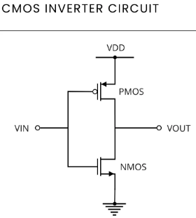
Common CMOS families include 4000B, 74HC, 74HCT, 74AC, 74ACT, 74LVC, 74AUP, and modern low-voltage families. 74HCT is especially useful because it is CMOS internally but accepts TTL-compatible input thresholds.
Important Characteristics
Voltage Compatibility
Always compare driver output limits with receiver input limits:
$$
NM_H = V_{OH(min)} - V_{IH(min)}
$$
$$
NM_L = V_{IL(max)} - V_{OL(max)}
$$
A positive margin is required; a larger positive margin is better.
Fan-Out
Fan-out is how many inputs one output can drive. For current-limited TTL:
$$
Fanout = \frac{I_{OL(max)}}{I_{IL(max)}}
$$
If a gate can sink 8 mA and each input needs 0.4 mA, then:
$$
Fanout = \frac{8}{0.4} = 20
$$
For CMOS, DC fan-out is often high, but capacitance limits edge speed.
Propagation Delay
Propagation delay is the time from input change to output response.

High-speed families reduce delay, but faster edges can increase EMI, ringing, and crosstalk.
Power
CMOS dynamic power is approximately:
$$
P = C_L V_{DD}^2 f
$$
For C_L = 50 pF, VDD = 5 V, and f = 1 MHz:
$$
P = 50 pF \times 25 \times 1 MHz = 1.25 mW
$$
Lowering voltage is powerful because power scales with VDD^2.
Interfacing Examples
- TTL output to
74HCinput at 5 V can fail because TTLVOH(min)may not reach CMOSVIH(min). - TTL output to
74HCTinput is usually appropriate becauseHCThas TTL-compatible thresholds. - 5 V output into 3.3 V CMOS input is unsafe unless the receiver is 5 V tolerant.
- 3.3 V output into 5 V input needs a margin check; do not assume it works.
Choosing a Family
| Need | Practical choice |
|---|---|
| 5 V hobby logic | 74HC or 74HCT |
| TTL input compatibility | 74HCT or 74ACT |
| 3.3 V general logic | 74LVC or 74AHC |
| Very low power | 74AUP |
| High speed | 74AC, 74AVC, or device-specific logic |
| Level translation | dedicated translator or tolerant 74LVC part |
Practical Reliability Rules
Place a 100 nF decoupling capacitor near every logic IC supply pin. Tie unused CMOS inputs to a valid level. Check absolute maximum ratings before mixing voltages. Keep fast traces short or controlled, and use series damping resistors when ringing becomes a problem.
Common Mistakes
- Assuming every 7400-series part has the same thresholds.
- Using
74HCwhen74HCTis needed for TTL compatibility. - Ignoring capacitive loading in CMOS fan-out.
- Forgetting decoupling capacitors.
- Leaving unused inputs floating.
Summary
Logic families define the real electrical behavior behind digital symbols. Select by supply voltage, thresholds, output drive, speed, power, load capacitance, temperature range, and availability. Verify compatibility from datasheets, not part-number familiarity.
Further Reading
- Texas Instruments, Logic Guide and standard-logic datasheets.
- Nexperia, Logic Family Specifications.
- ON Semiconductor and Toshiba 74-series selection guides.